Improvement of the electronic transformer for halogen lamps. Short circuit protection and starting of electronic transformers without load. Experiments with the tashibra electronic transformer. Electronic transformer circuit
Saving. At current prices for copper and steel, it is much cheaper to install a small board with a dozen parts and a small pulse transformer on a ferrite core.
Dimensions. An electronic transformer of similar power will be 5 times smaller in size and weigh as much less.
Stability. Most often, ETs already have built-in protection against short circuits and overcurrents (except for cheap Chinese ones), and the input voltage range is 100-270 volts. Agree - no ordinary transformer will provide stable output voltages with such a power supply variation.
Therefore, it is not surprising that radio amateurs have increasingly begun to use these pulse voltage converters to power their homemade designs. As a rule, such ETs are produced at a voltage of 12V, but increase or decrease it, as well as add a few more additional stress(for example, when creating a bipolar ULF power supply), you can wind up several turns on a ferrite ring.
![]()
And you don’t have to waste hundreds of meters of wire, because unlike ordinary transformer on hardware, there is approximately 1 turn per volt. And in more powerful electronic transformers, half a turn or less - look at the photo below, which shows 60 and 160 watt transformers.
![]()
In the first case, the 12-volt winding contains 12 turns, and in the second only 6. Therefore, to obtain an acceptable 300 volt output voltage (for power supply tube amplifier), you will need to wind only 150 turns. If you need to get a lower voltage than 12V, we tap from the standard winding. Typical:

Just keep in mind that most of these pulse transformers do not start with a load current of less than 1A. The minimum current may vary for different models. And here read more about the modifications of Chinese electric vehicles that allow them to start even at low currents and are not afraid of short circuits.
![]()
About the power of electronic transformers. Don't trust too much what is written on the ET case. If it is labeled as a 160-watt transformer, then already at 100 watts the heating will be such that there is a risk of failure of the output key transistors. Therefore, mentally divide it in half. Or install transistors on normal radiators, not forgetting about thermal paste.
![]()
Prices for electronic transformers are comparable to those on hardware. So a 160-watt ET costs $5 in our electrical goods store, and a weaker 60-watt ET costs $3. In general, the only drawback of electronic transformers can be considered an increased level of RF interference and lower operational reliability. If you burnt it, there is no point in repairing it; the probability of a successful repair is not high (unless, of course, the problem is in the fuse at the 220V input). It's cheaper to just buy a new one.
Discuss the article ELECTRONIC STOP TRANSFORMER
Review of popular Chinese electronic transformer TASCHIBRA. One fine day, a friend of mine brought a pulsed electronic transformer for repair to power the halogen lamps used to power it. The repair was a quick replacement of the dinistor. After giving it to the owner. I had a desire to make the same block for myself. First, I found out where he bought it and bought it for later copying.
Technical characteristics of TASCHIBRA TRA25
- Input AC 220V 50/60 Hz.
- AC 12V output. 60W MAX.
- Protection class 1.

Electronic transformer circuit

You can see the diagram in more detail. List of parts for manufacturing:
- n-p-n transistor 13003 2 pcs.
- Diode 1N4007 4 pcs.
- Film capacitor 10nF 100V 1 piece (C1).
- Film capacitor 47nF 250V 2 pcs (C2, C3).
- Dinistor DB3
- Resistors:
- R1 22 ohm 0.25W
- R2 500 kOhm 0.25W
- R3 2.5 ohm 0.25W
- R4 2.5 ohm 0.25W
Manufacturing a transformer on a W-shaped ferrite core from computer unit nutrition.

Primary winding contains 1-core wire, diameter 0.5 mm, length 2.85 m and 68 turns. The standard secondary winding contains a 4-core wire with a diameter of 0.5 mm, a length of 33 cm and 8-12 turns. The windings of the transformer must be wound in one direction. Winding the inductor on a ferrite ring with a diameter of 8 mm of the coil: 4 turns of green wire, 4 turns of yellow wire and not a full 1 (0.5) turn of red wire.


Dinistor DB3 and its characteristics:
- (I open - 0.2 A), V 5 is the voltage when open;
- Average maximum permissible value when open: A 0.3;
- In the open state, the pulse current is A 2;
- Maximum voltage (during closed state): V 32;
- Current in closed state: µA - 10; The maximum non-unlocking pulse voltage is 5 V.

This is how the design turned out. Of course the view is not very good, but I was convinced that it was possible to assemble it pulse device nutrition yourself.
Let's consider the main advantages, advantages and disadvantages of electronic transformers. Let's consider the scheme of their work. Electronic transformers appeared on the market quite recently, but managed to gain wide popularity not only in amateur radio circles.
Recently, articles based on electronic transformers have often been seen on the Internet: homemade power supplies, charging device and much more. In fact, electronic transformers are simple network transformers. This is the cheapest power supply. It's more expensive for a phone. The electronic transformer operates from a 220 volt network.
Device and principle of operation
Scheme of work
The generator in this circuit is a diode thyristor or dinistor. The 220 V mains voltage is rectified by a diode rectifier. There is a limiting resistor at the power input. It simultaneously serves as a fuse and protection against surges in mains voltage when turned on. The operating frequency of the dinistor can be determined from the ratings of the R-C chain.
In this way, the operating frequency of the generator of the entire circuit can be increased or decreased. The operating frequency in electronic transformers is from 15 to 35 kHz, it can be adjusted.

Transformer feedback wound on a small core ring. It contains three windings. The feedback winding consists of one turn. Two independent windings of master circuits. These are the basic windings of transistors of three turns.
These are equal windings. Limiting resistors are designed to prevent false triggering of transistors and at the same time limit the current. Transistors are used of high-voltage type, bipolar. MGE 13001-13009 transistors are often used. It depends on the power of the electronic transformer.
A lot also depends on the half-bridge capacitors, in particular the power of the transformer. They are used with a voltage of 400 V. From overall dimensions The core of the main pulse transformer also depends on the power. It has two independent windings: mains and secondary. Secondary winding with a rated voltage of 12 volts. It is wound based on the required output power.
The primary or network winding consists of 85 turns of wire with a diameter of 0.5-0.6 mm. Low-power rectifier diodes with a reverse voltage of 1 kV and a current of 1 ampere are used. This is the cheapest rectifier diode, which can be found in the 1N4007 series.
The diagram shows in detail the capacitor that sets the frequency of the dinistor circuits. A resistor at the input protects against voltage surges. Dinistor series DB3, its domestic analogue KN102. There is also a limiting resistor at the input. When the voltage on the frequency-setting capacitor reaches the maximum level, breakdown of the dinistor occurs. A dinistor is a semiconductor spark gap that operates at a certain breakdown voltage. Then it sends a pulse to the base of one of the transistors. The generation of the circuit begins.
Transistors operate in antiphase. Formed AC voltage on the primary winding of a transformer of a given dinistor operating frequency. On the secondary winding we get the required voltage. In this case, all transformers are designed for 12 volts.
Electronic transformers from Chinese manufacturer
It is designed to power 12 volt halogen lamps.

With a stable load, such as halogen lamps, such electronic transformers can operate indefinitely. During operation, the circuit overheats, but does not fail.
Operating principle
A voltage of 220 volts is supplied and rectified by the VDS1 diode bridge. Through resistors R2 and R3, capacitor C3 begins to charge. The charge continues until the DB3 dinistor breaks through.
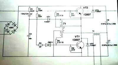
The opening voltage of this dinistor is 32 volts. After it opens, voltage is supplied to the base of the lower transistor. The transistor opens, causing self-oscillation of these two transistors VT1 and VT2. How do these self-oscillations work?
Current begins to flow through C6, transformer T3, base control transformer JDT, transistor VT1. When passing through the JDT it causes VT1 to close and VT2 to open. After this, the current flows through VT2, through the base transformer, T3, C7. Transistors constantly open and close each other, working in antiphase. At the midpoint, rectangular pulses appear.
The conversion frequency depends on the inductance of the feedback winding, the capacitance of the transistor bases, the inductance of transformer T3 and capacitances C6, C7. Therefore, it is very difficult to control the conversion frequency. The frequency also depends on the load. To force the opening of transistors, 100-volt accelerating capacitors are used.
To reliably close the dinistor VD3 after generation occurs, rectangular pulses are applied to the cathode of the diode VD1, and it reliably closes the dinistor.
In addition, there are devices that are used for lighting, power powerful halogen lamps for two years, and work faithfully.
Power supply based on an electronic transformer

The mains voltage is supplied to the diode rectifier through a limiting resistor. The diode rectifier itself consists of 4 low-power rectifiers with a reverse voltage of 1 kV and a current of 1 ampere. The same rectifier is located on the transformer block. After rectifier constant pressure smoothed by an electrolytic capacitor. The charging time of capacitor C2 depends on resistor R2. At maximum charge, the dinistor is triggered, causing a breakdown. An alternating voltage is generated at the primary winding of the transformer at the operating frequency of the dinistor.
The main advantage of this circuit is the presence of galvanic isolation from a 220 volt network. The main disadvantage is the low output current. The circuit is designed to power small loads.
Electronic transformersDM-150T06A

Current consumption 0.63 ampere, frequency 50-60 hertz, operating frequency 30 kilohertz. Such electronic transformers are designed to power more powerful halogen lamps.
Advantages and Benefits
If you use the devices for their intended purpose, then there is good function. The transformer does not turn on without an input load. If you simply plugged in a transformer, it is not active. You need to connect a powerful load to the output for work to begin. This feature saves energy. For radio amateurs who convert transformers into a regulated power supply, this is a disadvantage.
You can implement an auto-on system and a protection system against short circuit. Despite its shortcomings, an electronic transformer will always be the cheapest type of half-bridge power supply.
You can find higher quality inexpensive power supplies with a separate oscillator on sale, but they are all implemented on the basis of half-bridge circuits using self-clocking half-bridge drivers, such as the IR2153 and the like. Such electronic transformers work much better, are more stable, have short circuit protection, and have a surge filter at the input. But the old Taschibra remains indispensable.
Disadvantages of electronic transformers
They have a number of disadvantages, despite the fact that they are made according to good schemes. This is the lack of any protection in cheap models. We have simplest scheme electronic transformer, but it works. This is exactly the scheme implemented in our example.
There is no line filter at the power input. At the output after the inductor there should be at least a smoothing electrolytic capacitor of several microfarads. But he is also missing. Therefore, at the output of the diode bridge we can observe an impure voltage, that is, all network and other noise is transmitted to the circuit. At the output we get a minimum amount of noise, since it is implemented.
The operating frequency of the dinistor is extremely unstable and depends on the output load. If without an output load the frequency is 30 kHz, then with a load there can be a fairly large drop to 20 kHz, depending on the specific load of the transformer.
Another disadvantage is that the output of these devices is variable frequency and current. To use electronic transformers as a power supply, you need to rectify the current. You need to straighten it with pulse diodes. Conventional diodes are not suitable here due to the increased operating frequency. Since such power supplies do not implement any protection, if you just short-circuit the output wires, the unit will not just fail, but explode.
At the same time, during a short circuit, the current in the transformer increases to a maximum, so the output switches (power transistors) will simply burst. The diode bridge also fails, since they are designed for an operating current of 1 ampere, and in the event of a short circuit, the operating current increases sharply. The limiting resistors of the transistors, the transistors themselves, the diode rectifier, and the fuse, which should protect the circuit but does not, also fail.
Several other components may fail. If you have such an electronic transformer unit, and it accidentally fails for some reason, then it is not advisable to repair it, since it is not profitable. Just one transistor costs $1. A ready block food can also be bought for $1, brand new.
Power of electronic transformers
You can find it on sale today different models transformers ranging from 25 watts to several hundred watts. A 60 watt transformer looks like this.

The manufacturer is Chinese, producing electronic transformers with a power of 50 to 80 watts. Input voltage from 180 to 240 volts, network frequency 50-60 hertz, operating temperature 40-50 degrees, output 12 volts.
After everything that was said in the previous article (see), it seems what to do pulse block power supply from an electronic transformer is quite simple: install a rectifier bridge at the output, a voltage stabilizer if necessary, and connect the load. However, this is not quite true.
The fact is that the converter does not start without a load or the load is not sufficient: if you connect an LED to the output of the rectifier, of course, with a limiting resistor, you will be able to see only one LED flash when turned on.
To see another flash, you will need to turn off and turn on the converter to the network. In order for the flash to turn into a constant glow, you need to connect an additional load to the rectifier, which will simply take away the useful power, turning it into heat. Therefore, this scheme is used in the case where the load is constant, for example, a DC motor or an electromagnet, which can only be controlled via the primary circuit.
If the load requires a voltage of more than 12V, which is produced by electronic transformers, you will need to rewind the output transformer, although there is a less labor-intensive option.
Option for manufacturing a switching power supply without disassembling the electronic transformer
The diagram of such a power supply is shown in Figure 1.
Figure 1. Bipolar power supply for amplifier
The power supply is made on the basis of an electronic transformer with a power of 105W. To manufacture such a power supply, you will need to make several additional elements: a mains filter, matching transformer T1, output choke L2, VD1-VD4.
The power supply has been operating for several years with a ULF power of 2x20W without any complaints. At rated mains voltage 220V and load current 0.1A output voltage block 2x25V, and when the current increases to 2A, the voltage drops to 2x20V, which is quite enough for normal operation amplifier
The matching transformer T1 is made on a K30x18x7 ring made of M2000NM ferrite. The primary winding contains 10 turns of PEV-2 wire with a diameter of 0.8 mm, folded in half and twisted into a bundle. The secondary winding contains 2x22 turns with a midpoint, the same wire, also folded in half. To make the winding symmetrical, you should wind it in two wires at once - a bundle. After winding, to obtain the midpoint, connect the beginning of one winding to the end of the other.
You will also have to make the inductor L2 yourself; for its manufacture you will need the same ferrite ring as for the transformer T1. Both windings are wound with PEV-2 wire with a diameter of 0.8 mm and contain 10 turns.
The rectifier bridge is assembled on KD213 diodes, you can also use KD2997 or imported ones, it is only important that the diodes are designed for an operating frequency of at least 100 KHz. If instead of them you put, for example, KD242, then they will only heat up, and you will not be able to get the required voltage from them. The diodes should be installed on a radiator with an area of at least 60 - 70 cm2, using insulating mica spacers.
C4, C5 are made up of three parallel-connected capacitors with a capacity of 2200 microfarads each. This is usually done in all switching power supplies in order to reduce the overall inductance of the electrolytic capacitors. In addition, it is also useful to install ceramic capacitors with a capacity of 0.33 - 0.5 μF in parallel with them, which will smooth out high-frequency vibrations.
It is useful to install an input surge filter at the input of the power supply, although it will work without it. As an input filter choke, a ready-made DF50GTs choke was used, which was used in 3USTST TVs.
All units of the block are mounted on a board made of insulating material in a hinged manner, using the pins of the parts for this purpose. The entire structure should be placed in a shielding case made of brass or tin, with holes provided for cooling.
A correctly assembled power supply does not require adjustment and starts working immediately. Although, before placing the block in the finished structure, you should check it. To do this, a load is connected to the output of the block - resistors with a resistance of 240 Ohms, with a power of at least 5 W. It is not recommended to turn on the unit without load.
Another way to modify an electronic transformer
There are situations when you want to use a similar switching power supply, but the load turns out to be very “harmful”. The current consumption is either very small or varies widely, and the power supply does not start.
A similar situation arose when they tried to put it in a lamp or chandelier with built-in electronic transformers instead. The chandelier simply refused to work with them. What to do in this case, how to make it all work?
To understand this issue, let's look at Figure 2, which shows a simplified circuit of an electronic transformer.
Figure 2. Simplified circuit of an electronic transformer
Let's pay attention to the winding of the control transformer T1, highlighted by a red stripe. This winding provides current feedback: if there is no current through the load, or it is simply small, then the transformer simply does not start. Some citizens who bought this device connect a 2.5W light bulb to it, and then take it back to the store, saying it doesn’t work.
And yet it's enough in a simple way You can not only make the device work with virtually no load, but also provide short circuit protection in it. The method of such modification is shown in Figure 3.
Figure 3. Modification of the electronic transformer. Simplified diagram.
In order for the electronic transformer to operate without load or with minimal load, current feedback should be replaced with voltage feedback. To do this, remove the current feedback winding (highlighted in red in Figure 2), and instead solder a jumper wire into the board, naturally, in addition to the ferrite ring.
Next, a winding of 2 - 3 turns is wound onto the control transformer Tr1, this is the one on the small ring. And there is one turn per output transformer, and then the resulting additional windings are connected as indicated in the diagram. If the converter does not start, then you need to change the phasing of one of the windings.
The resistor in the feedback circuit is selected within the range of 3 - 10 Ohms, with a power of at least 1 W. It determines the depth of feedback, which determines the current at which generation will fail. Actually, this is the current of short-circuit protection. The greater the resistance of this resistor, the lower the load current the generation will fail, i.e. short circuit protection triggered.
Of all the improvements given, this is perhaps the best. But this will not prevent you from supplementing it with another transformer, as in the circuit in Figure 1.
Fluorescent and halogen lamps are gradually becoming a thing of the past, giving way to LED lamps. In the lamps where they were used, unnecessary electronic transformers remained, which were responsible for igniting these lamps. It seems that what is unnecessary belongs in the trash heap. But that's not true. From these transformers you can assemble powerful blocks power supplies that can power power tools, LED strips and much more.
Electronic transformer device
The massive transformers we are accustomed to have recently begun to be replaced by electronic ones, which are cheap and compact. The dimensions of the electronic transformer are so small that they are built into the housings of compact fluorescent lamps(CFL).
All such transformers are made according to the same circuit; the differences between them are minimal. The circuit is based on a symmetrical self-oscillator, otherwise called a multivibrator.
They consist from a diode bridge, transistors and two transformers: matching and power. These are the main parts of the scheme, but not all. In addition to them, the circuit includes various resistors, capacitors and diodes.
Schematic diagram of an electronic transformer.
In this scheme D.C. from the diode bridge it goes to the transistors of the autogenerator, which pump energy into the power transformer. The ratings and type of all radio components are selected so that a strictly defined voltage is obtained at the output.
If you turn on such a transformer without a load, the self-generator will not start and there will be no voltage at the output.
DIY assembly according to the diagram
![]() Electronic ballast can be bought in a store or found in your bins, but the most interesting option would be to assemble an electronic transformer with your own hands. It is assembled quite simply, and most of the necessary parts can be pick through broken power supplies and in energy-saving lamps.
Electronic ballast can be bought in a store or found in your bins, but the most interesting option would be to assemble an electronic transformer with your own hands. It is assembled quite simply, and most of the necessary parts can be pick through broken power supplies and in energy-saving lamps.
- Required components: A diode bridge with a reverse voltage of at least 400 V and a current of at least 3 A or four diodes with the same characteristics.
- 5 A fuse.
- Symmetrical dinistor DB3.
- Resistor 500 kOhm.
- 2 resistors 2.2 Ohm, 0.5 W.
- 2 bipolar transistors MJE13009.
- 3 film capacitors 600 V, 100 nF.
- 2 toroidal cores.
- Lacquered wire 0.5 mm².
- Wire in regular insulation 2.5 mm².
- Radiator for transistors.
- Bread board.
It all starts with a breadboard on which you will install all the radio components. You can buy two types of boards on the market - with one-sided metallization on brown fiberglass.
And with two-way through, on green.
The choice of board determines how much time and effort you will spend on assembling the project.
Brown boards are of disgusting quality. The metallization on them is made in such a thin layer that In some places there are visible tears on it. It is poorly wetted by solder, even if you use good flux. And everything that was successfully soldered comes off along with the metallization at the slightest effort.
Green ones cost one and a half to two times more, but the quality is okay. Metallization on them has no problems with thickness. All holes in the board are tinned at the factory, so the copper does not oxidize and there are no problems during soldering.
You can find and buy these breadboards either in the nearest radio store or on Aliexpress. In China they cost half as much, but delivery will have to wait.
Choose radio components with long leads, they will be useful to you when installing the circuit. If you are going to use used parts, be sure to check their functionality and absence of external damage.
The only part you have to make yourself is the transformer.
The matching must be wound with a thin wire. Number of turns in each winding:
- I - 7 turns.
- II - 7.
- III - 3.
Don't forget to secure the windings with tape, otherwise they will fall apart.
The power transformer consists of only two windings. Wind the primary with 0.5mm² wire, and the secondary with 2.5mm². The primary and secondary consist of 90 and 12 turns, respectively.
For soldering, it is better not to use “old-fashioned” soldering irons - they can easily burn temperature-sensitive radioelements. It’s better to take a soldering iron with power control; they don’t overheat, unlike the first ones.
Install the transistors on the radiators in advance. Doing this on an already assembled board is extremely inconvenient. You need to assemble the circuit from small parts to large ones. If you install the large ones first, they will interfere when soldering the small ones. Take this into account.
When assembling, look at schematic diagram, all connections of radio elements must comply with it. Insert the pins of the parts into the holes on the board and bend them in the desired direction. If the length is not enough, extend them with wire. After soldering, glue the transformers to the board with epoxy resin.
After assembly, connect a load to the terminals of the device and make sure that it works.
Conversion into a power supply
![]() It happens that power tool batteries fail, and there is no opportunity to buy a new one. In this case, an adapter in the form of a power supply will help. After a little modification, you can assemble such an adapter from an electronic transformer.
It happens that power tool batteries fail, and there is no opportunity to buy a new one. In this case, an adapter in the form of a power supply will help. After a little modification, you can assemble such an adapter from an electronic transformer.
Parts needed for remodeling:
- NTC thermistor 4 Ohm.
- Capacitor 100 µF, 400 V.
- Capacitor 100 uF, 63V.
- Film capacitor 100 nF.
- 2 resistors 6.8 Ohm, 5 W.
- Resistor 500 Ohm, 2 W.
- 4 diodes KD213B.
- Radiator for diodes.
- Toroidal core.
- Wire with a cross-section of 1.2 mm².
- A piece of circuit board.
Before work, check if you forgot any part. If all the parts are in place, begin converting the electronic transformer into a power supply.
Solder a 400 V, 100 µF capacitor to the output of the diode bridge. To reduce the charging current of the capacitor, solder a thermistor into the gap in the power wire. If you forget to do this, the first time you turn it on, your diode bridge will burn out.
Disconnect the second winding of the matching transformer and replace it with a jumper. Add one winding on both transformers. Make one turn on the matching one, two on the power one. Connect the windings to each other by soldering two parallel-connected 6.8 Ohm resistors into the wire gap.
To make a choke, wind 24 turns of 1.2 mm² wire around the core and secure it with tape. Then, on the breadboard, assemble the remaining radio components according to the diagram and connect the assembly to the main circuit. Don't forget to install diodes on the radiator, when working under load they get very hot.
Secure the entire structure in any suitable case and the power supply can be considered assembled.
After final assembly, plug the device into the network and check its operation. It should produce a voltage of 12 volts. If the power supply supplies them, you have done your job perfectly. If it doesn't work, check to see if you took a non-working transformer.